How to use Node js to interact with IIOT platform without iot device
In this tutorial, we'll demonstrate an experiment using a Node.js script to interact with the IIOT platform via MQTT. This script will show how to connect to an MQTT broker, publish sensor data (temperature and humidity) at regular intervals, and handle connection errors. This experiment simulates data transmission from an IoT device to the IIOT platform, providing a comprehensive guide for beginners to get started.
Prerequisites
- Node.js: Ensure that Node.js is installed on your machine. It can be downloaded from nodejs.org.
- MQTT Broker Details: Acquire the hostname, port, username, and password for the MQTT broker from the IIOT platform.
- Create a Project: Follow the instructions in this section to establish a new project.
- Create an Asset: Refer to the relevant section to define and integrate an asset into your project.
- Create a Parameter: Refer the relevant section to configure and set up parameters for your asset.
Step 1:
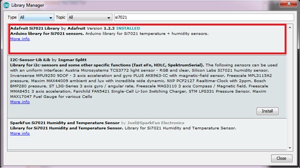
Install the MQTT Library
You need to install the necessary Node.js library (mqtt). The latest stable version can be found in the npm registry and can be installed using the following command:
npm install mqtt or yarn add mqtt
Step 2:
Retrieve MQTT Credentials
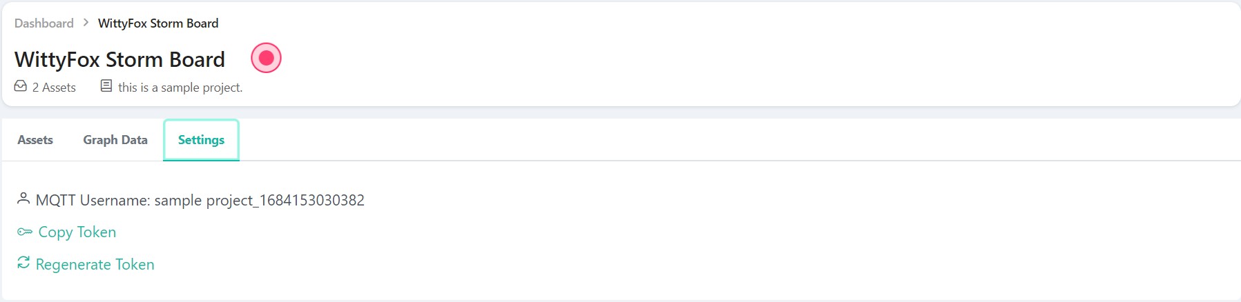
Log in to the IIOT Platform and navigate to the project tab. From there, you can retrieve your MQTT username and copy the token from the settings section, which serves as your MQTT password.
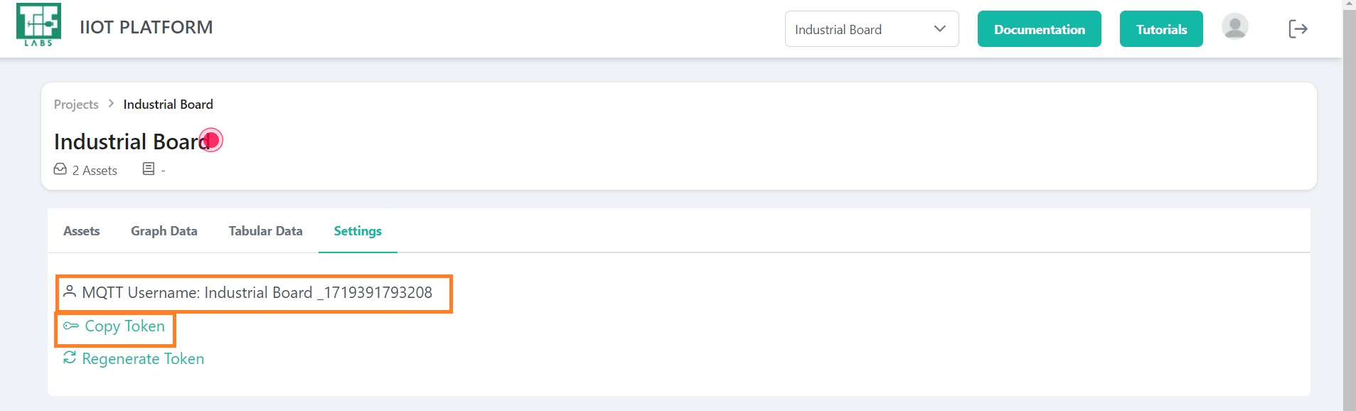
Fig 1: Settings Section
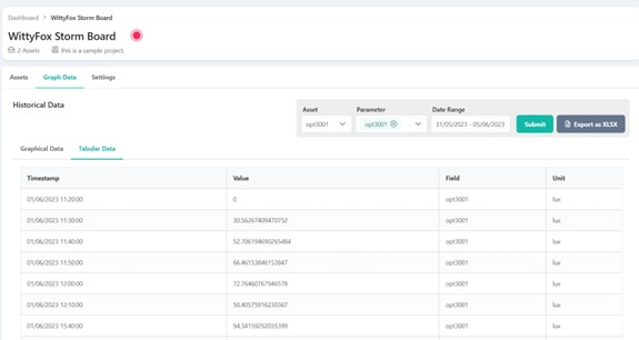
Additionally, you will need the MQTT topic, which can be found by navigating to the assets and parameters sections.
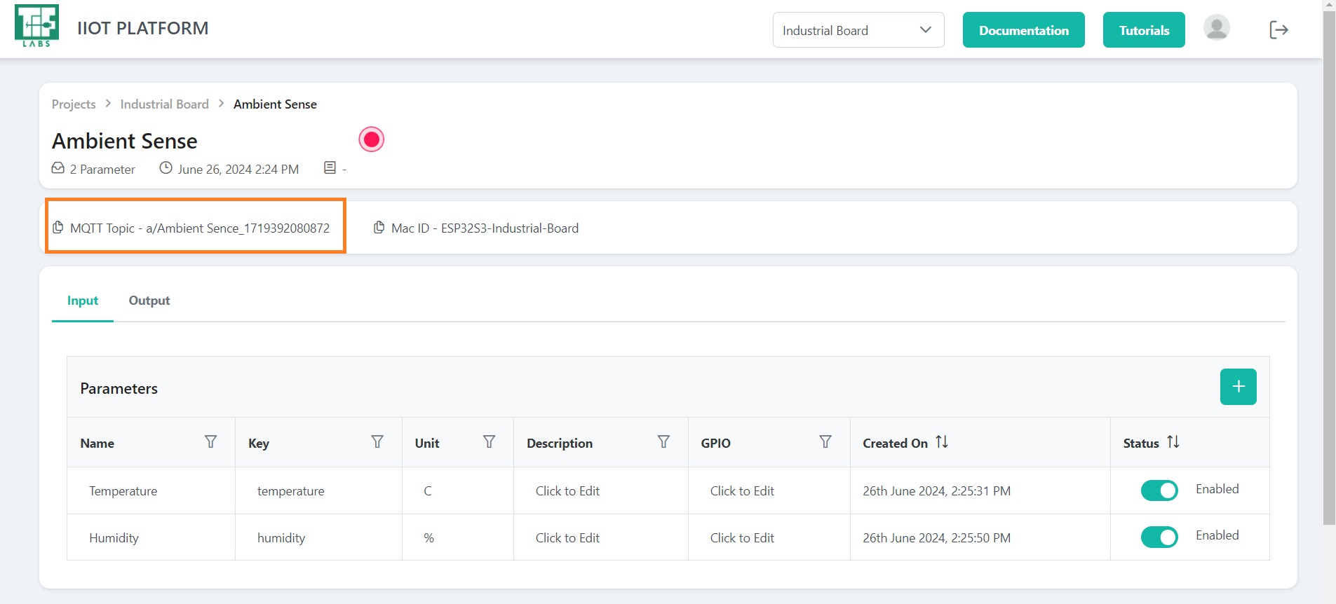
Fig 2: Retrive topic
Step 3:
Develop the script
Create a new file named iiot-mqtt-script.js and incorporate the following code. This script will establish a connection to the MQTT broker, publish sensor data, and handle any potential errors.
Program:
const mqtt = require("mqtt");

// Constants for your credentials and the MQTT topic
const USERNAME = ""; // username
const PASSWORD = ""; //password
const PUBLISH_TOPIC = ""; //topic

// Configure MQTT client
const client = mqtt.connect("mqtt://iiotif.com:1883", {
  username: USERNAME,
  password: PASSWORD,
  clientId: `iotif_client_${Math.random().toString(16).slice(3)}`,
  clean: true,
  connectTimeout: 4000,
  reconnectPeriod: 1000,
});

client.on("connect", () => {
  console.log("Connected to MQTT broker");

  // Subscribe for debugging
  client.subscribe(PUBLISH_TOPIC, { qos: 1 }, (err) => {
    if (err) {
      console.error("Error subscribing to topic:", err);
    } else {
      console.log(`Subscribed to ${PUBLISH_TOPIC}`);
    }
  });

  // Generate simulated data
  const generateRandomData = () => {
    const temperature = 15 + Math.random() * 15; // Range: 15–30
    const humidity = 20 + Math.random() * 30; // Range: 20–50
    return {
      temperature: parseFloat(temperature.toFixed(2)),
      humidity: parseFloat(humidity.toFixed(2)),
    };
  };

  // Publish the message
  const publishMessage = () => {
    const message = generateRandomData();
    message.timestamp = Date.now();
    client.publish(
      PUBLISH_TOPIC,
      JSON.stringify(message),
      { qos: 1, retain: false },
      () => {
        console.log("Message published:", message);
      }
    );
  };

  // Publish every 5 seconds
  setInterval(publishMessage, 5000);
});

// Debug incoming messages
client.on("message", (topic, message) => {
  console.log(`Received message on ${topic}: ${message.toString()}`);
});

// Handle errors
client.on("error", (err) => {
  console.error("Failed to connect to MQTT broker:", err);
});

// Handle disconnections
client.on("close", () => {
  console.log("Disconnected from MQTT broker");
});
Explanation:
MQTT Client Configuration
- Credentials: Replace
USERNAME,PASSWORD, andPUBLISH_TOPICwith your actual MQTT credentials and topic. - Connection: The MQTT client connects to the broker at
mqtt://iiotif.com:1883using the provided credentials.
const client = mqtt.connect("mqtt://iiotif.com:1883", {
  username: USERNAME,
  password: PASSWORD,
  clientId: `iotif_client_${Math.random().toString(16).slice(3)}`,
  clean: true,
  connectTimeout: 4000,
  reconnectPeriod: 1000,
});
Data Generation
-
generateRandomData Function: Simulates sensor data with small variations. This function uses
Math.sinandMath.costo create minor fluctuations around base values for temperature and humidity. -
The key used during parameter creation should be reused here as the value for the variable.
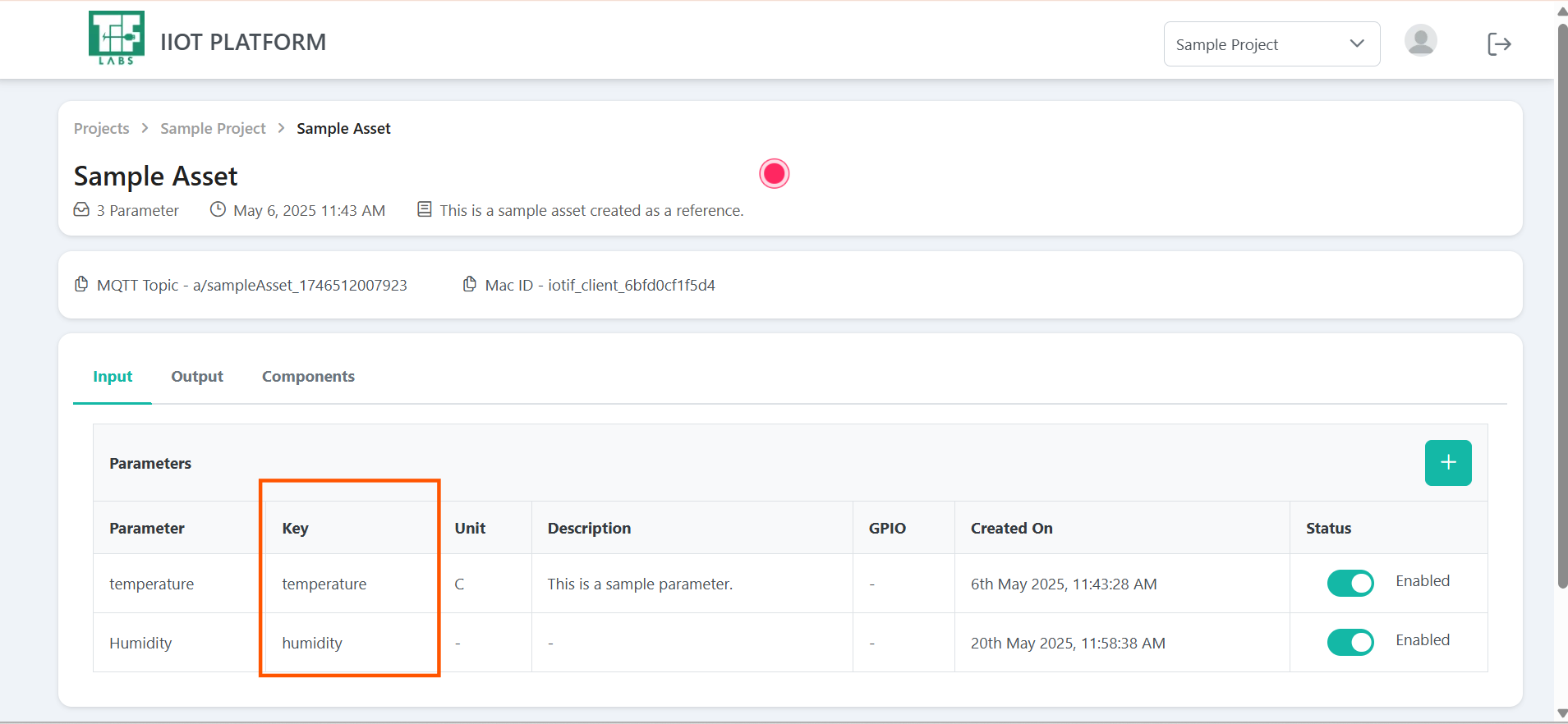
Fig 3: Retrive key
const generateRandomData = () => {
  const temperature = 15 + Math.random() * 15; // 15–30
  const humidity = 20 + Math.random() * 30; // 20–50
  return {
    temperature: parseFloat(temperature.toFixed(2)),
    humidity: parseFloat(humidity.toFixed(2)),
  };
};
Message Publishing
- publishMessage Function: Publishes the generated sensor data to the specified topic every 5 seconds.
const publishMessage = () => {
  const message = generateRandomData();
  message.timestamp = Date.now();
  client.publish(
    PUBLISH_TOPIC,
    JSON.stringify(message),
    { qos: 1, retain: false },
    () => {
      console.log("Message published:", message);
    }
  );
};

setInterval(publishMessage, 5000);
- Publishing Interval: Set to 5 seconds using
setInterval.
setInterval(publishMessage, 5000);
Error Handling
- client.on("error"): Logs any connection errors to assist with troubleshooting.
client.on("message", (topic, message) => {
  console.log(`Received message on ${topic}: ${message.toString()}`);
});
Step 4:
Executing the Script
- Open a Terminal: Navigate to your project directory.
- Execute the Script: Run the script using Node.js with the following command:
node iiot-mqtt-script.js
Step 5:
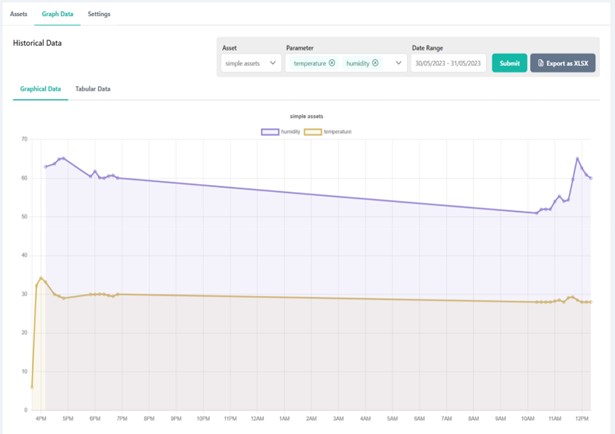
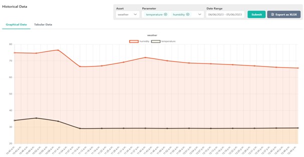
Monitor Data on the IIOT Platform
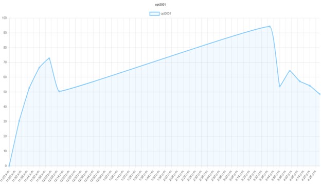
The console will indicate "Connected to MQTT broker" upon a successful connection. Additionally, every 5 seconds, the console will display the published message.
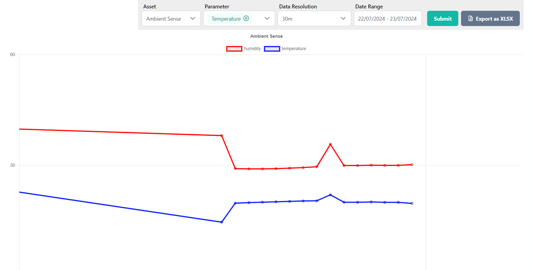
Fig 4: Graphical Data Representation
Troubleshooting
- Connection Errors: Confirm that your MQTT broker details (host, port, username, password) are accurate.
- Network Issues: Verify your network connection and check any firewall settings that might be blocking MQTT traffic.
- Broker Availability: Ensure that the MQTT broker is available and operational.
Conclusion
This experiment illustrates how to use Node.js to interact with an IIOT platform via MQTT. The script establishes a connection to the broker, publishes sensor data, and manages potential errors. By following this guide, you can replicate and tailor the experiment to meet your specific requirements.