OPT3001 with ESP32
In this tutorial, we'll demonstrate how to connect the OPT3001 ambient light sensor to the ESP32 board and transmit data to the IIOT platform. The OPT3001 is a single-chip lux metre that measures the intensity of light. The OPT3001 is designed for systems that create light-based experiences for humans and is an ideal replacement for photodiodes, photoresistors, or other ambient light sensors. Here is a picture of the OPT3001 ambient light sensor and the ESP32 board.
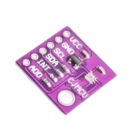
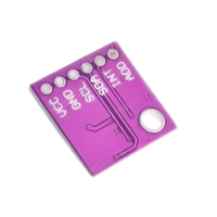
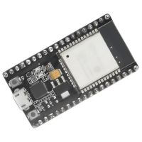
Fig 1: OPT3001 And ESP32
Step 1:
Hardware Setup
The OPT30001 Ambient Light Sensor is directly compatible with the ESP32 Board via I2C ports P9 and P10. These are the connections you need to make from the ESP32 board -> OPT3001:
| ESP32 board | OPT3001 |
|---|---|
| 3.3 V | VCC |
| GND | GND |
| P9(SCL) | SCL |
| P10(SDA) | SDA |
Fig 2: OPT3001 And ESP32 Connections
Step 2:
Retrieve MQTT Credentials
Go to the project tab. From there, you can copy your MQTT username and token inside the setting section and your MQTT topic inside the assets section that is needed in the program.

Fig 3: Settings Section
Step 3:
Install Required Libraries
(Downloading the libraries):
Connect your ESP32 board with OPT3001 Sensor. To send the sensor readings to the IIOT Platform, install the ClosedCube OPT3001 and PubSubClient libraries using the Library Manager in the Arduino IDE. Go to Sketch > Include Library > Manage Librariesand search for the library name in the library manager.
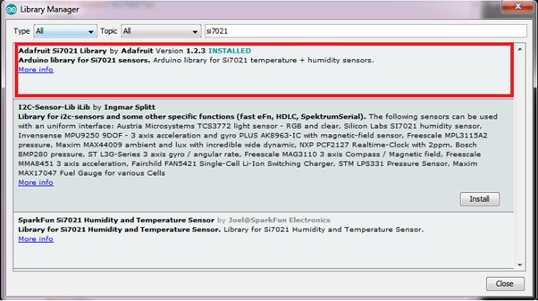
Fig 4: Arduino Library Manger
You can download IIOT_Platform_ESP32 library from HERE. [DOWNLOAD THE LIBRARY]
Step 4:
Implement Arduino Sketch
First, you need to include all the liberties. The Wire.h library uses the I2C communication protocol, the ClosedCube_OPT3001.h library reads from the sensor, and the IIOTPlateform.h library sends the data to the IIOT platform. Then, create a ClosedCube_OPT3001 object called opt3001 and an IIOTPlatform object called obj. Next, you have to set the network credentials in the initWiFi() section, the MQTT credentials in the setCredentials() section, and the MQTT topic in the setTopic() section for the ESP32 board. Next, there are two main functions: configureSensor() and printResult(). The first function is used to initialise and calibrate the sensor, and the second is used to get the output, whether it gets the data or not. In the loop function, we get the data using the printResult() function; after that, we store the data in a variable and send this data to the IIOT Platform using the addParameter() and publish() functions.
Program
#include <Wire.h>
#include <ClosedCube_OPT3001.h>
#include "IIOTPlatform.h"

IIOT obj;
ClosedCube_OPT3001 opt3001;
#define OPT3001_ADDRESS 0x44
void setup()
{
  Serial.begin(115200);
  obj.debugMode(true);
  obj.initWifi("wifi_ssid", "WiFi_password");
  obj.setCredentials("mqtt_username", "mqtt_password");
  obj.initMqtt();
  obj.setTopic("mqtt_topic");
opt3001.begin(OPT3001_ADDRESS);
Serial.println("ClosedCube OPT3001 Arduino Test");
Serial.print("OPT3001 Manufacturer ID");
Serial.println(opt3001.readManufacturerID());
Serial.print("OPT3001 Device ID");
Serial.println(opt3001.readDeviceID());
configureSensor();
printResult("High-Limit", opt3001.readHighLimit());
printResult("Low-Limit", opt3001.readLowLimit());
Serial.println("----");
}
void configureSensor()
{
OPT3001_Config newConfig;
newConfig.RangeNumber = B1100;
newConfig.ConvertionTime = B0;
newConfig.Latch = B1;
newConfig.ModeOfConversionOperation = B11;
 	OPT3001_ErrorCode errorConfig = opt3001.writeConfig(newConfig);
  	if (errorConfig != NO_ERROR)
    	 printError("OPT3001 configuration", errorConfig);
  	else {
    	OPT3001_Config sensorConfig = opt3001.readConfig();
    	Serial.println("OPT3001 Current Config:");
    	Serial.println("------------------------------");
    	Serial.print("Conversion ready (R):");
    	Serial.println(sensorConfig.ConversionReady,HEX);
   	Serial.print("Conversion time (R/W):");
    	Serial.println(sensorConfig.ConvertionTime, HEX);
    	Serial.print("Fault count field (R/W):");
    	Serial.println(sensorConfig.FaultCount, HEX);
    	Serial.print("Flag high field (R-only):");
    	Serial.println(sensorConfig.FlagHigh, HEX);
    	Serial.print("Flag low field (R-only):");
    	Serial.println(sensorConfig.FlagLow, HEX);
    	Serial.print("Latch field (R/W):");
    	Serial.println(sensorConfig.Latch, HEX);
    	Serial.print("Mask exponent field (R/W):");
    	Serial.println(sensorConfig.MaskExponent, HEX);
    	Serial.print("Mode of conversion operation (R/W):");
    	Serial.println(sensorConfig.ModeOfConversionOperation, HEX);
    	Serial.print("Polarity field (R/W):");
    	Serial.println(sensorConfig.Polarity, HEX);
    	Serial.print("Overflow flag (R-only):");
    	Serial.println(sensorConfig.OverflowFlag, HEX);
    	Serial.print("Range number (R/W):");
    	Serial.println(sensorConfig.RangeNumber, HEX);
    	Serial.println("------------------------------");
 	 }
}
void printResult(String text, OPT3001 result) {
  if (result.error == NO_ERROR) {
    Serial.print(text);
    Serial.print(": ");
    Serial.print(result.lux);
    Serial.println(" lux");
  }
  else {
    printError(text,result.error);
  }
}
void printError(String text, OPT3001_ErrorCode error) {
  Serial.print(text);
  Serial.print(": [ERROR] Code #");
  Serial.println(error);
}
void loop()
{
  OPT3001 result = opt3001.readResult();
  printResult("OPT3001", result);

  float opt3001 = result.lux;
  obj.addParameter("opt3001", opt3001);
  obj.publish();
  delay(1000);
}
Step 5:
Upload Code to ESP32 Board
After inserting your network credentials, MQTT credentials and MQTT topic in the code, upload the code to your ESP32 board.
Step 6:
Monitor Data on IIOT Platform
Allow the programme to run for a while so that you can view some useful data on the website. A sample set of readings stored on the website is shown below in graphical format and tabular data:

Fig 5: Graphical Data Representation
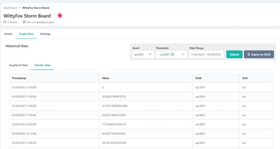
Fig 6: Tabular Data Representation
Conclusion
In this tutorial, we looked at utilising an ESP32 board and an OPT3001 ambient light sensor to send data from an OPT3001 sensor.